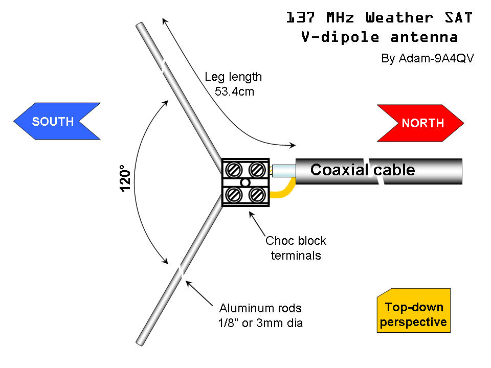
If you’re interested in receiving weather satellite images, one of the first steps is building a suitable antenna. In this post, I’ll walk you through the process of creating a simple 137MHz antenna designed for NOAA/METEOR satellite reception. The design is based on the brilliant work by Adam-9A4QV, and the total cost was around £10, with materials sourced from Screwfix.
Materials You Will Need:
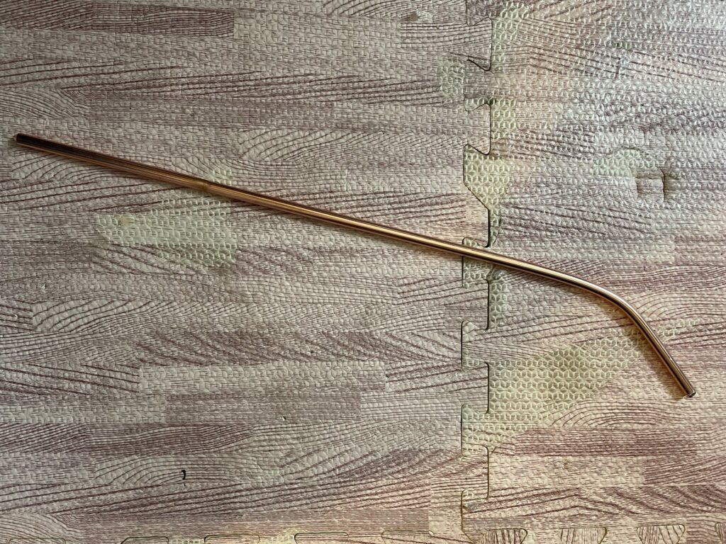
- 1.5m copper earth bar – £3
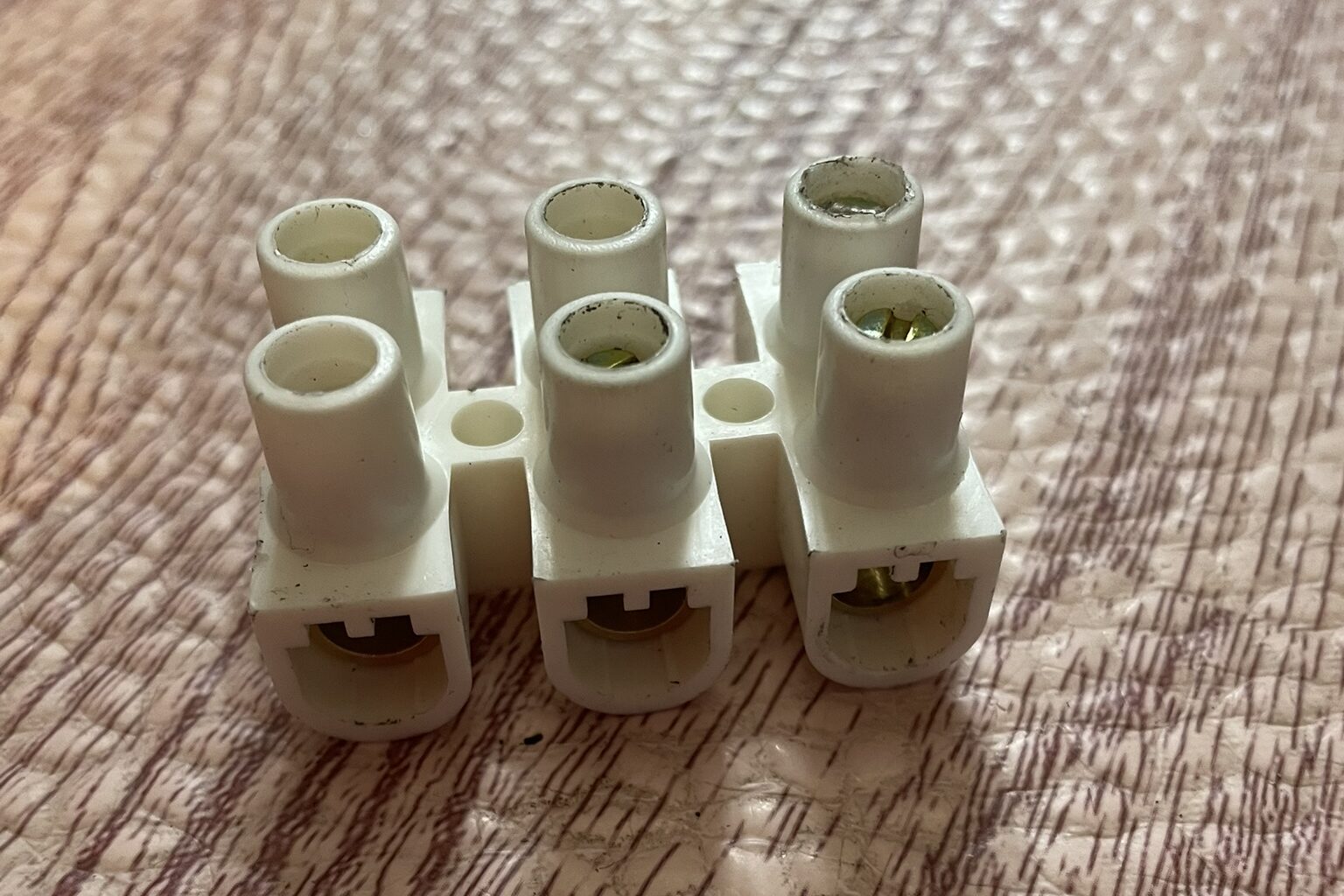
- 60 Amp block connectors (strip) – £2
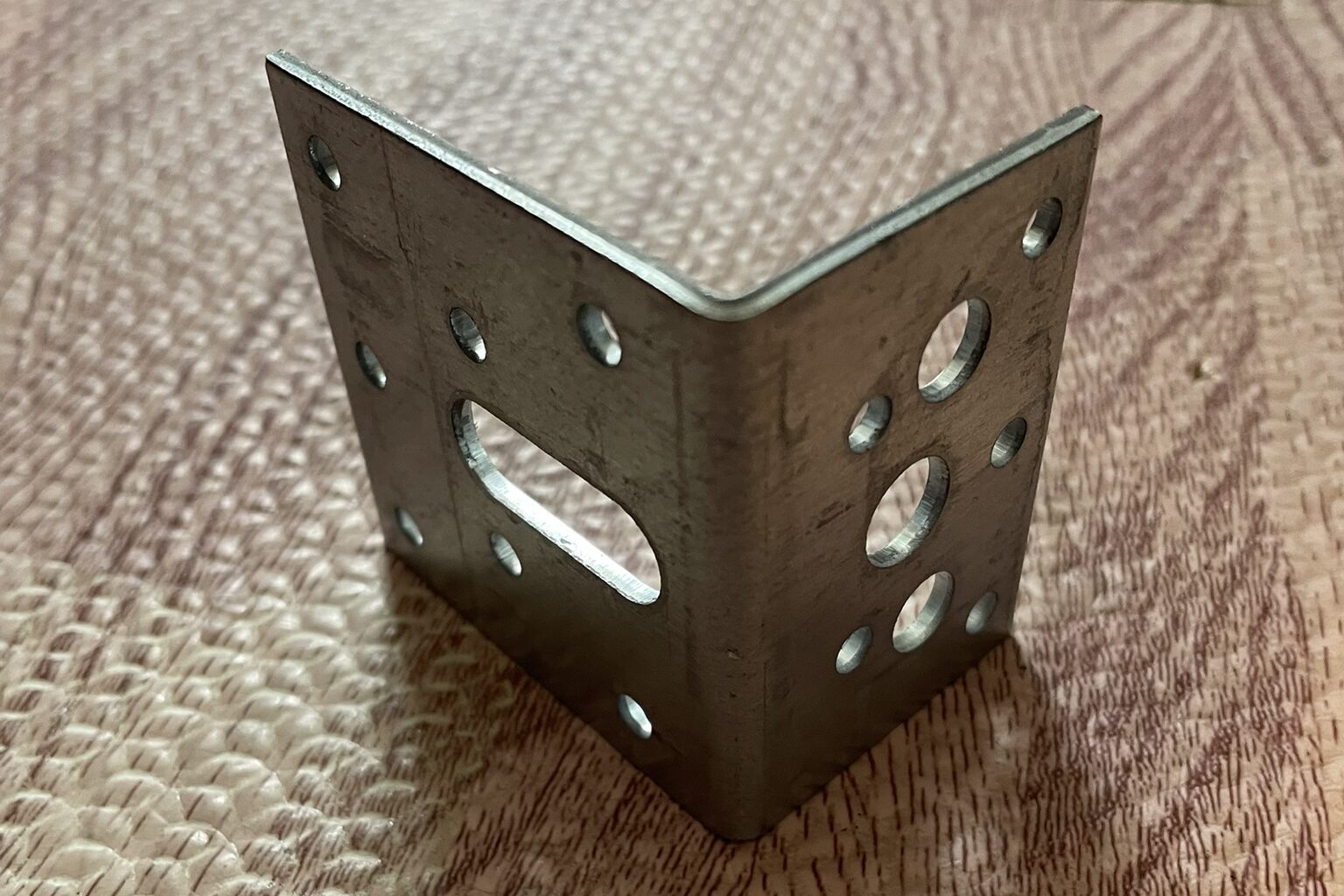
- Metal L bracket – £1
- 1m of coaxial cable – £3
- PL259 connector – £1
All of these materials are easy to find at your local hardware store. The copper earth bar forms the main structure of the antenna, while the block connectors help with assembling the elements without soldering. The L bracket will act as a mount, and the coaxial cable is for connecting the antenna to your receiver.
Tools Required:
- Wire cutters/strippers
- Small screwdriver (for the block connectors)
- Pliers
- Measuring tape
- Drill (for mounting)
- Soldering Iron (for the PL259 connector)
Step-by-Step Build Guide
- Prepare the Elements:
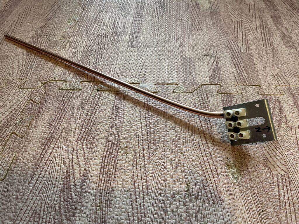
- Bend each end of the copper earth bar by approximately 30 degrees.
- Cut the copper earth bar into two sections with length of approximately 53.4 cm each.
- Connect the Elements:
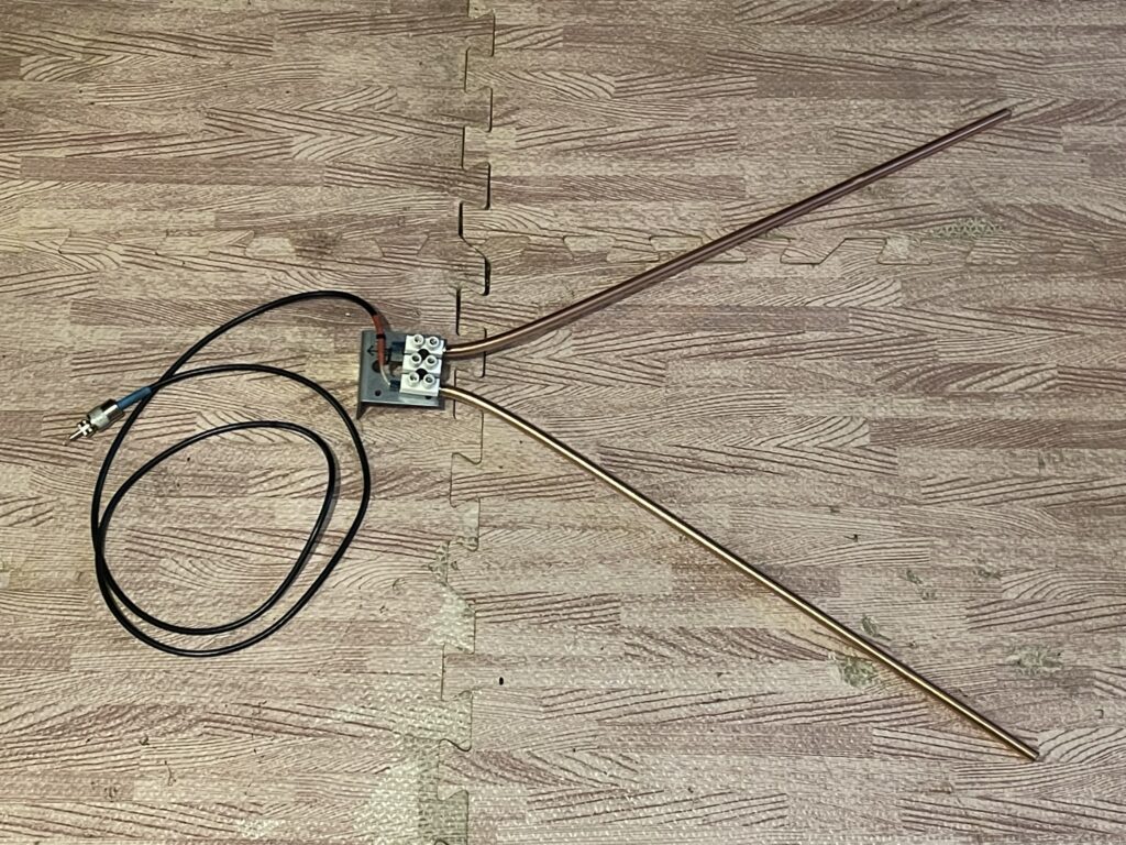
- Using the 60 Amp block connectors, join the two elements with a slight gap between them. This will act as the feed point for your coaxial cable.
- Mounting the Antenna:
- Use the metal L bracket to mount the antenna. You can either drill the bracket into a wall or clamp it onto a mast, depending on your setup. This will provide the necessary support for the antenna to stand upright and be positioned for optimal signal reception.
- Attach the Coaxial Cable:
- Strip one end of the coaxial cable. Attach the centre conductor to one side of the block connector. Connect the shielding braid to the other side of the connector.
- Secure the connection tightly with a small screwdriver, ensuring there’s no short between the centre conductor and the shielding.
- Fine-Tuning:
- Position the antenna in such a way so the coaxial cable end points NORTH and the open end of the antenna is pointing SOUTH.
Results and Performance
Once assembled, the antenna can be connected to your SDR receiver or satellite tracking system. I’ve been using it with my NOAA/METEOR satellite system based on the R2Cloud project, and it has performed incredibly well considering the low cost and simplicity of the design.
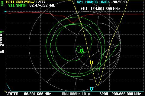
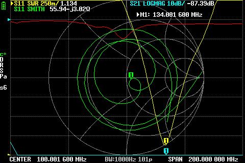
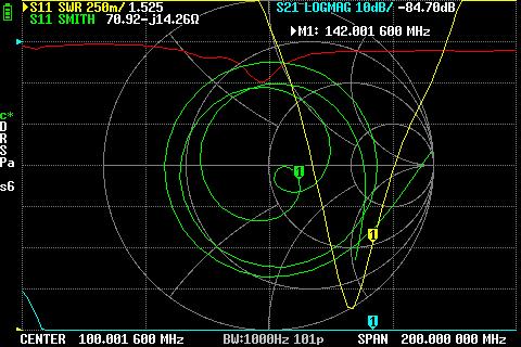
After completing the build, I tested the antenna using a Vector Network Analyser (VNA) to verify its performance. The results were quite promising. The antenna was able to receive across a broad frequency range from 124 MHz to 142 MHz, with a Standing Wave Ratio (SWR) of no more than 1.577, ensuring minimal signal loss across this range. It was particularly resonant at 134 MHz, where the SWR dropped to an impressive 1.134, indicating excellent efficiency. Additionally, the antenna showed 55-70 Ohms of resistance across the frequency range, which is close to the ideal impedance for most receivers, ensuring strong and stable signal reception.
At around £10 in materials and less than an hour of build time, this project is a fantastic introduction to the world of satellite weather reception. Whether you’re tracking NOAA or METEOR satellites, this antenna should provide a solid performance on a budget.
If you give this a try, feel free to share your results in the comments below or connect with me through the blog. I’m always excited to see how others adapt or improve upon these designs!
Happy building!

Leave a Reply